SDF-Based UI in Unity
Introduction⌗
Unity’s default UI system presents several challenges not usually present in other popular UI frameworks. One such challenge is the lack of any flexible, built-in rectangle rendering system. Rectangles are the building blocks of most modern user interfaces, and clean, crisp lines and properly rounded corners can mean the difference between a decent graphical interface and a great one. The built-in Unity solution is to use sprites for any rectangular element which is not a filled, solid-color, unrounded rectangle. This approach can lead to less flexible UI elements, blurry lines, and inaccurate corner and border-width rendering. Additionally, trying to compensate for these issues can result in increased video memory usage and a mess of image resources required to render all necessary variants of rectangles used by an application. In this article, we’ll implement a custom UIRect component to solve these problems. All source code referenced in this article is available on Github.
This article is intended for use within the Unity UI system. While Unity does provide a new and more flexible UI Toolkit, it is not yet stable and does not currently support world-space UI.
Prerequisites⌗
This series assumes a basic understanding of C# and shaders, as well as the following tools:
- Unity (with an existing project targeting Android)
- An IDE compatible with Unity, e.g. Visual Studio, Jetbrains Rider, or Visual Studio Code
Signed Distance Fields⌗
Signed Distance Fields, or SDFs, are the basis of a graphics rendering technique which take a mathematical approach to rendering geometry as opposed to a mesh-based approach. SDFs are calculated in screen space, generally using the UV coordinates of a simple mesh as sample inputs to a signed distance function. A signed distance function takes in a point and additional parameters used to define a shape, and returns the distance of the supplied point to the line or surface defined by the function. All points that share the same distance value are referred to as an isoline (2D) or isosurface (3D). The signed portion of SDF means that any point inside the SDF is negative, while any point outside the SDF is positive, and any point exactly on the isoline or isosurface has a distance of 0. The simplest SDF is that of a circle, which is defined by the distance of the sample point to the center of the circle. Any point inside the circle is negative, any point with a distance from the center equal to the radius of the circle has a value of 0, and any point outside the circle is positive. If you’d like to learn more about SDFs or are looking for a reference for SDFs to represent various shapes, I highly recommended Inigo Quilez’ articles and videos.
For our purposes, we’ll use an SDF for a rounded rectangle. This SDF takes in a 2D point, the half-size dimensions of the rectangle, and the radius for each corner of the rectangle. Due to the symmetries of a rectangle, the SDF of a rectangle essentially moves the sample point to the upper right quadrant of the rectangle and tests against the half-size dimensions of the rectangle, adjusting for the radius of the corner closest to the point. The following code is adapted from Inigo Quilez’ Rounded Box - exact implementation:
float sdRoundedBox(float2 pt, float2 halfDimensions, float4 radii)
{
    radii.xy = (pt.x > 0.0) ? radii.zw : radii.yx;
    radii.x = (pt.y > 0.0) ? radii.x : radii.y;
    float2 q = abs(pt) - halfDimensions + radii.x;
    return min(max(q.x, q.y), 0.0) + length(max(q, 0.0)) - radii.x;
}
UIRect Shader⌗
In order to use the SDF technique described above, we’ll need to create a custom shader to use with our UIRect component. We’ll start with the default UI shader, which can be found in the editor archives. Find the editor version you’re using and select the Built-In Shaders option from the dropdown for your platform. Inside the downloaded archive, you should find the default UI shader under DefaultResourcesExtra/UI/UI-Default.shader. Copy this shader into your project, changing the name to something indicative of our special rectangle UI shader, like UIRect.shader.
Open the shader, and we’ll begin modifying the default shader by changing the name from UI/Default to the name we specified early, UI/UIRect. For values that remain consistent for each component of a mesh, we would traditionally use uniform variables to control the shader. Due to limitations with the way Unity UI rendering works, we’ll need to pack any additional parameters into the vertex data passed to the shader using the additional UV channels. To do this, we’ll need to modify the appdata_t struct as well as the v2f rect. We’ll need the following parameters for the UI Rect shader:
- Width & height of the rect, as described by its
RectTransform - Border width
- Radius for each corner
The width, height, and border width can be packed into a 4-dimensional vector in a UV channel, and the radii will use an additional 4-dimensional vector and UV channel. After adding these two vectors to the per-vertex and per-fragment data structures, they should appear as shown below:
struct appdata_t
{
    float4 vertex   : POSITION;
    float4 color    : COLOR;
    float2 texcoord : TEXCOORD0;
    float4 sdfData : TEXCOORD1;
    float4 radii : TEXCOORD2;
    UNITY_VERTEX_INPUT_INSTANCE_ID
};

struct v2f
{
    float4 vertex   : SV_POSITION;
    fixed4 color    : COLOR;
    float2 texcoord  : TEXCOORD0;
    float4 worldPosition : TEXCOORD1;
    float4 sdfData : TEXCOORD2;
    float4 radii : TEXCOORD3;
    float4 mask : TEXCOORD4;
    UNITY_VERTEX_OUTPUT_STEREO
};
Be sure to copy the vectors to the v2f structure in the vertex shader.
v2f vert(appdata_t v)
{
    v2f OUT;

    ...

    OUT.sdfData = v.sdfData;
    OUT.radii = v.radii;

    ...

    return OUT;
}
We’ll also add a uniform parameter called Softness which will be used to control the appearance at the edges of the shape.
Properties
{
    ...
    _Softness ("Softness", float) = 0.5
    ...
}

...

// In shader code
float _Softness
Additionally, we’ll need to add the SDF function shown above so that we can reference it in the fragment shader. In the fragment shader, after the color is sampled from the texture, we want to compute the signed distance of the current fragment’s UV coordinates. In order to achieve proper scaling and respect the aspect ratio of the rect, the dimensions passed in will be the half-size rect dimensions and the point passed in will be the UV coordinate of the fragment remapped from 0-1 to the range of -RectHalfSize, +RectHalfSize.
float2 dimensions = IN.sdfData.xy;
float2 pt = (IN.texcoord - float2(0.5, 0.5)) * dimensions;
float distance = sdRoundedBox(pt, dimensions / 2, IN.radii);
Now that we have the distance value, we can adjust the output alpha of the fragment so that fragments outside the rect are transparent. The simplest approach is to use an inverted step function with the edge set at 0, so that any values with a signed distance greater than 0 have an alpha of 0. However, we can improve the appearance of the edge by using a smoothstep function to gradually fade the edge from opaque to transparent. We can use the Softness variable to define the range over which the alpha is faded in/out by fading across the isoline at 0-distance to the isoline at the distance Softness inside the rect. The output of the smoothstep function is inverted so that the output value fades from 1 to 0 instead of 0 to 1.
color.a *= 1 - smoothstep(-_Softness, 0, distance);
The last change is to adjust the output alpha again based on the border width. For this implementation, we are not considering drawing a border and a fill on the same UI Rect, so a border width greater than half the shorter side of the rect results in a completely filled rect. We can use the border width similarly to the alpha adjustment in the previous step, except the smoothstep will operate over the range from -BorderWidth to -BorderWidth + Softness.
float borderWidth = IN.sdfData.z;
color.a *= 1 - smoothstep(0 - borderWidth, 0 - (borderWidth + _Softness), sdf);
At this point, the shader is ready. The next step is to create a new class to control the shader.
Unity UI Graphic⌗
Graphic is the base class for all visual Unity UI components. In order to create the SDF-based rect component, we’ll need to inherit from Graphic. All of the functionality we need to add can be handled by overriding the OnPopulateMesh method. This method is responsible for generating the mesh data that will be sent to the shader for rendering a specific instance of the Graphic.
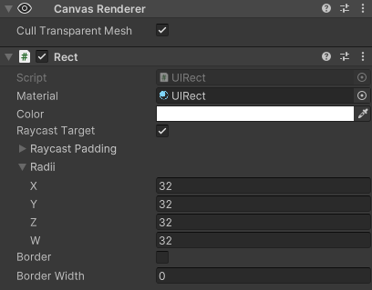
We’ll begin by creating a new class that inherits from Graphic. I’ll be calling the class UIRect, but any name will do. The class will expose 3 serialized fields to be set in the editor:
- Radii (Vector4) - the radius of each corner of the rect, beginning with the bottom-left and continuing clockwise
- Border (boolean) - whether a border should be rendered or the the rect should be rendered filled
- Border Width (float) - width of the border to render if
Borderis set to true
Once the serialized fields are defined, the only remaining step is to override the OnPopulateMesh method and populate the mesh buffer with the data used by the shader. The complete class looks as follows:
[RequireComponent(typeof(CanvasRenderer))]
public class UIRect : Graphic
{

    [SerializeField] private Vector4 _radii;
    [SerializeField] private bool _border;
    [SerializeField] private float _borderWidth;


    protected override void OnPopulateMesh(VertexHelper vh)
    {
        base.OnPopulateMesh(vh);

        var r = GetPixelAdjustedRect();
        var v = new Vector4(r.x, r.y, r.x + r.width, r.y + r.height);

        //SDF data:
        // x: width
        // y: height
        // z: borderWidth
        // w: unused
        Vector4 sdfData = new()
        {
            x = r.width,
            y = r.height,
            z = _border ? _borderWidth : Mathf.Max(r.width, r.height)
        };

        vh.Clear();
        UIVertex vert = new()
        {
            position = new Vector3(v.x, v.y),
            color = color,
            uv0 = new Vector2(0f,0f),
            uv1 = sdfData,
            uv2 = _radii
        };
        vh.AddVert(vert);
        vert = new()
        {
            position = new Vector3(v.x, v.w),
            color = color,
            uv0 = new Vector2(0f,1f),
            uv1 = sdfData,
            uv2 = _radii
        };
        vh.AddVert(vert);
        vert = new()
        {
            position = new Vector3(v.z, v.w),
            color = color,
            uv0 = new Vector2(1f,1f),
            uv1 = sdfData,
            uv2 = _radii
        };
        vh.AddVert(vert);
        vert = new()
        {
            position = new Vector3(v.z, v.y),
            color = color,
            uv0 = new Vector2(1f,0f),
            uv1 = sdfData,
            uv2 = _radii
        };
        vh.AddVert(vert);

        vh.AddTriangle(0, 1, 2);
        vh.AddTriangle(2, 3, 0);
    }
}
Using the UIRect Component⌗
The UIRect component can be used anywhere a built-in UI element can. Add the UIRect component to a gameobject under a canvas (if you’ve specified that UIRect requires a CanvasRenderer as shown above that component will also be added). In order to use the UIRect shader, we also need to create a material that specifies that shader. In the project window, right-click, select Create->Material, and name the material UIRect. In the inspector, open the Shader dropdown and select UI->UIRect. Lastly, select the UIRect gameobject in the scene and set the material to newly created UIRect material.
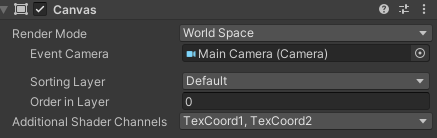
One important caveat is that the Canvas component that the UIRect is a child of must be configured to send the additional UV channels using the Additional Shader Channels property. This should be set to TexCoord1, TexCoord2 so that the additional information used by the UIRect shader is properly sent.
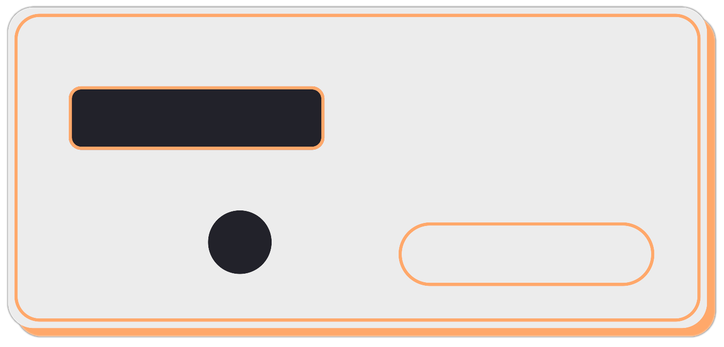
Multiple UIRects can be combined to create more fully featured UI components like buttons with outlines. Setting the corner radius to half the width/height of a rect can be used to create circles or pills.
Further Improvements⌗
At this point, the UIRect is a complete and usable component. While these won’t be implemented as part of this article, here are a few suggestions for possible future improvements:
- Add custom editor UI to make working with the component in the editor simpler. Some ideas:
- Hide/disable border width when border is disabled
- Properly label radii corners
- Allow locking radii together so that they share the same values automatically
- Render the border and fill on the same UIRect, with separate color parameters for border and fill
- Support gradients (use separate colors for each vertex)
- Add an SDF-based drop shadow effect